ATARI DOUBLE
PIA
by ZZT
PIAis the acronym for Peripheral Interface Adaptor .
It's a input and output data chip. Connect the CPU of a computer with the outside world and can be used for input or output.
On the inner side, which is connected directly to the CPU, it has 8 pins that correspond to the data bus, andsome control lines and two in/out ports, 8 pins each, getting or giving a byte depending ifare reading or writing. A byte comprises values between 0 and 255, depending on the combination of ones and zeros. The versatility of the PIA is that you can program it anddecide how you want to operate their ports, which are inputs and which are outputs.

The PIA in the Atari is the 6520, 40 DIP format.

It consists of two ports of 8 bits each. Port A (PA) and Port B (PB).

In Atari XLmodelsport A is dedicated to read the two joysticks, four pins for each:
|
PUERTO A |
||||||||
|
STICK |
JOYSTICK 1 |
JOYSTICK 2 |
||||||
|
PORT |
PA0 |
PA1 |
PA2 |
PA3 |
PA4 |
PA5 |
PA6 |
PA7 |
|
PIN PIA |
2 |
3 |
4 |
5 |
6 |
7 |
8 |
9 |
|
USE |
UP |
DOWN |
LEFT |
RIGHT |
UP |
DOWN |
LEFT |
RIGHT |
|
data bus |
D0 |
D1 |
D2 |
D3 |
D4 |
D5 |
D6 |
D7 |
As shown on the table, the joystick 1 corresponds to the first half of the byte obtained and corresponding values between 0 and 15. J oystick 2 carries the other bytehalf, values between 16 and 255. During initialization the entire port is configured as inputs.
The port B is a completely different story:

|
PORT B |
||||||||
|
PORT |
PB0 |
PB1 |
PB2 |
PB3 |
PB4 |
PB5 |
PB6 |
PB7 |
|
PIN PIA |
10 |
eleven |
12 |
13 |
14 |
fifteen |
16 |
17 |
|
USE |
MMU 9 |
MMU 18 |
|
|
|
|
|
MMU 6 |
|
data bus |
D0 |
D1 |
D2 |
D3 |
D4 |
D5 |
D6 |
D7 |
Only three pins are used, PB0 (pin10), PB1 (pin11) PB7 (pin17). All goes to Memory Management Unit MMU, which it is responsible for enable Basic ROM, Operating System ROMand others. Pins (pin12) PB3 (pin13) PB4 (pin14) PB5 (PIN15) PB6 (pin16) remains not used. During system initialization entire port is configured as outputs, regardless if they are in use or not pins.
How PIA talks with the CPU?
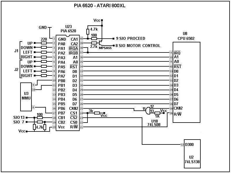
The connection between the PIA and CPU aremuch simpler thanappears :
- Pin 1 goes to GND or ground
- Pines 2 3 4 5 6 7 8 9 go to the joysticks
- Pins 10 and 11 go to the MMU
- Pines 12 13 14 15 16 not used
- Pin 17 goes to MMU
- Pin 18 or CB1 SIO(pin13) INTERRUPT
- Pin 19 or CB2SIO (PIN7) COMMAND
- Pin 20 is Vcc power + 5Volts
- Pin 21 is Read Write or R / W.
It goes to the CPU pin 14
- Pin 22 is CSO or Chip Select 0, enables high level, goes to Vcc together with CS1
- Pin 23 is CS2 or Chip Select 2 enables low level.
He goes to U2 74LS138 decoder chip pin12
- Pin 24 is CS1 or Chip Select 0, enables high level.
He goes to Vcc in conjunction with CS0
- Pin 25 is 02 or clock signal.
He goes to U18 pin 11 and from pin 12 thereof to the CPU pin39
- Pin 26 27 28 29 30 31 32 33 is the data bus.
Correspond exactly with the CPU (pin 26 27 28 29 30 31 32 33)
- Pin 34 signal Reset, active low.
It goes to the CPU pin 40
- Pin 35 RS1, goes to the CPU address bus A0 (pin 9)
- Pin 36 RS0, goes to the CPU address bus A1 (pin 10)
- Pin 37 IRQB and pin 38to the CPU IRQ (pin 4)
- Pin 38 IRQA and pin 37 to the CPU IRQ (pin 4)
- CA1 (pin40) SIO(pin 9) PROCEED
- CA2 (pin39) SIO(pin 8) MOTOR CONTROL (controls the motor of the cassette deck)
What you need to pay attention?
Well ... everything!
But most important is how the CPU "talks" to the PIA.
This is done basically between RS1 RS0-A1-A0 and the data bus.
Depending on
the value of A0 and A1 RS0 and RS1 affects and that is what allowsto program and access certain PIA functions.
The signal reset is... reset.
The CK02 signal is the clock signal.
And the most important, although not connected to the CPU, it is CS2 which is connected to a decoder chip, which activates the PIA whenever a POKE is made between an addressfrom 54016 (D300) to 54271 ( D3FF).
PIA setup may seem a bit complicated, but it is not. At poweron,the operating system automatically configures, and according tothe Atari functions, the port A as all input and port B all output. This means that the port A data flow from the joysticks to the CPU and the B port in oposite, from the CPU to the port and from there to MMU. This remains unless modified by the user or programmer.
Using PORTA
Port A is the most useful serves as the joystick plugs allow us to connect DB9 plugs right there and use it at will. Instead, make any modifications in portB without knowing what is being done, will cause the Atarito crash (or worst).
In order to configure the port A of the PIA as desire you have to put three pokes:
|
PORT AS INPUT |
PORT AS OUTPUT |
|
POKE 54018,56 |
POKE 54018,56 |
|
POKE 54016,0 |
POKE 54016,255 |
|
POKE 54018,60 |
POKE 54018,60 |
Inshort, a simple couple of instructions in Basic, modify the behavior of the PIA.
A value of 0 onmemoryposition 54016 sends eight zeros to register, sets PACTLall port A as input data and a value of 255 in 54016 sends eight ones causing all port as dataoutput.
Port PACTL means port A control.
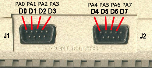
Here the order regarding the PIA and the data bus that corresponds to each pin of the two joysticks in a 800XL shown.
Nowwe will investigate a little further.
Today thereare many devices that can do the same as an Atari and with more speed and many more features, but perhaps not as easy as using an Atari, to learn. So mine intention to give concoct this is simply a didactic way, showing that even such a basic microcomputer as an Atari is able to control external devices with relative ease between programming and some hardware.
So that we could use this?
The answer is no one, because as from the factory, the port A of Atari seteado all as inputs, you can:
- Connect 8 switches, for example from some kind of machine.
Even using optocouplers or LDRs a position detection mode.
- Make a special joystick like Track and Field

- Use a joystick lever (PA0 PA1 PA2 PA3) and PA4 PA5 PA7 PA6 as 4 extra buttons.
Half entrance, exit half
Here is a good example of using 4- bit and 4- bit output as input, this can be done with the following formula:
|
PUERTO A / HALF IN - HALF OUT |
|
|
POKE 54018.52 |
|
|
POKE 54016.16 |
D7> 00001111 |
|
POKE 54018.60 |
|
In this example, D0 (PA0) D1 (PA1) D2 (PA2) D3 (PA3) are at level 1, therefore will be output. And D4 (PA4) D5 (PA5) D6 (PA7) D7 (PA7) are at level 0, so will be inputs. Thanks this arrangement the joystick 1 is input and two outputs joy. This configuration is used by a chip, multiplex and connect upto 8 joysticks:

http://raster.atariportal.cz/hw/mj8_2007.gif
Departure
Play of light:

Input and output
Eproms recorder and reader:

-
second PIA
Now, an output port is mostly for large projects. Although a port of 8 bits can be "larger" multiplexing, their management becomes more complex in terms of software and hardware. A second PIA, with both unemployed ports, solves this problem.
Add a second PIA is super easy in the schematic can be seen as.:

All lines that unite the Atari are shared, except CS2 (pin 23), which must be attached to pin 10 of the chip U2 (74LS138).
CB1 (pin 18), CA1 (pin 40) remain unused and bind to Vcc with resistance 4.7K.
And another good thing here, CB2 (pin 19) is another departure, as well as CA2 (pin 39). So are two ports of 8 bits, plus two extra outputs.
The dotted line letsyou
choose between D500 and D100,
Atari PIA is located in the memory D300. The second can be addressed or D100 D500. With a small detail that analyze.
Consider the following comparison table between PIA addresses the Atari and the second:
PIA 1 D3XX
This is the normal PIA, which comes standard on the Atari.
|
PIA 1 PORT |
PIA 1 PORT B |
||
| D300 | 54016 | D301 | 54017 |
| D302 | 54018 | D303 | 54019 |
PIA 2 D5XX
PIA seguna D5XX can be selected, but this direction also uses the cartridge.
As not be used simultaneously.
Sure, if you will not use cartridge, no problem.
Oryou
can get a switch thatoccur
disabling the PIA when you wantto
use the cartridge.
|
PIA 2 Port A |
PIA 2 Port B |
||
| D500 | 54528 | D501 | 54529 |
| D502 | 54530 | D503 | 54531 |
PIA 1 D1XX
And also you can connect to D1XX, but in the first Atari this direction controls the ANTIC chip, so I think, and I have not checked, could have conflicos with certain programs or games.
So far the tests I've done have not caused me problems.
|
PIA 2 Port A |
PIA 2 Port B |
||
| D100 |
53504 |
D101 |
53505 |
| D102 |
53506 |
D103 |
53507 |
And now programming.
PIA 2 Port A in D500
|
PORT AS INLET |
PORT AS OUTPUT |
|
POKE 54530.56 |
POKE 54530.56 |
|
POKE 54528.0 |
POKE 54528.255 |
|
POKE 54530.60 |
POKE 54530.60 |
PIA 2 Port B in D500
|
PORT AS INLET B |
PORT B as output |
|
POKE 54531.56 |
POKE 54531.56 |
|
POKE 54529.0 |
POKE 54529.255 |
|
POKE 54531.60 |
POKE 54531.60 |
PIA 2 Port A in D100
|
PORT AS INLET |
PORT AS OUTPUT |
|
POKE 53506.56 |
POKE 53506.56 |
|
POKE 53504.0 |
POKE 53504.255 |
|
POKE 53506.60 |
POKE 53506.60 |
PIA 2 Port B in D100
|
PORT AS INLET |
PORT AS OUTPUT |
|
POKE 53507.56 |
POKE 53507.56 |
|
POKE 53505.0 |
POKE 53505.255 |
|
POKE 53507.60 |
POKE 53507.60 |
54016 (W / R) reads or writes data from two terminals and one if the driver of PACTL bit2 (location 54018) is one. The writing on the steering control if bit 2 PACTL is zero.
Wverything described here been madestep by step having the knowledge of what is being doing.
Notice:a bad connection can damage your Atari!!! So be careful and do it at your own risk.
Warning: Attempts to modify your Atari without the proper knowledge, and skills, can result in a serious damage to your atari. Do it at your own risk.
o